10.4.1 MIM Option A
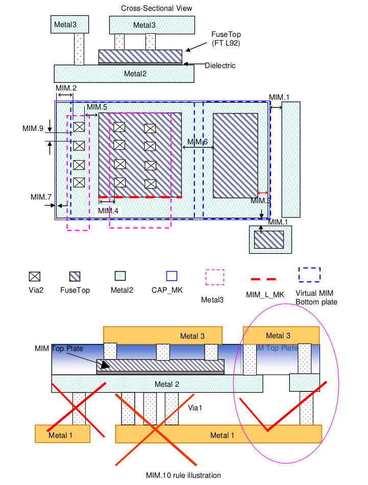
This section describes rules for MIM (Metal-insulator-Metal) capacitor. FuseTop layer defines the top plate of MIM capacitor and Metal2 layer defines MIM bottom plate. Area of the MIM is determined by FuseTop Layer.
RULE NO. |
DESCRIPTION |
LAYOUT RULE |
MIM.1 |
Minimum MiM bottom plate (1) spacing to the bottom plate metal (whether adjacent MiM or routing metal) |
1.2 |
MIM.2 |
Minimum MiM bottom plate (1) overlap of Via2 layer [This is applicable for via2 within 1.06um oversize of FuseTop layer (referenced to virtual bottom plate)] |
0.4 |
MIM.3 |
Minimum MiM bottom plate overlap of Top plate |
0.6 |
MIM.4 |
Minimum MiM top plate (FuseTop) overlap of Via2 |
0.4 |
MIM.5 |
Minimum spacing between top plate and the Via2 connecting to the bottom plate |
0.4 |
MIM.6 |
Minimum spacing between unrelated top plates |
0.6 |
MIM.7 |
Min FuseTop enclosure by CAP_MK |
0 |
MIM.8a |
Minimum MIM cap area (defined by FuseTop area) |
5*5 um2 |
MIM.8b |
Maximum single MIM Cap area (Use multiple MIM caps in parallel connection if bigger capacitors are required) |
100*100 um2 |
MIM.9 |
Min. via spacing for sea of via on MIM top plate |
0.5 |
MIM.10 |
|
|
MIM.11 |
Bottom plate of multiple MIM caps can be shared (for common nodes) as long as total MIM area with that single common plate does not exceed “MIM.8b” rule. |
|
MIM.12* |
For MIM need to identify its’ length and width, use MIM_L_MK to mark MIM capacitor’s length |
|
Guideline |
There cannot be any sensitive matching analog circuitry underneath MIM. |
Note
Checked by virtual MiM bottom plate which defines as: ((FuseTop@1.06) AND (Metal2 interact FuseTop))